SPARCserver 1000
| 501-2336 |
0MB FRU
w/o SPARC Module
|
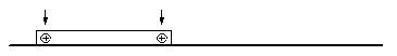
Backplane Guide Pins
Remove two screws from the System Board XDbus connector before installing
the system board in backplanes with guide pins. Guide pins were added to the
backplane in March 1994
by ECO WO_05457
.
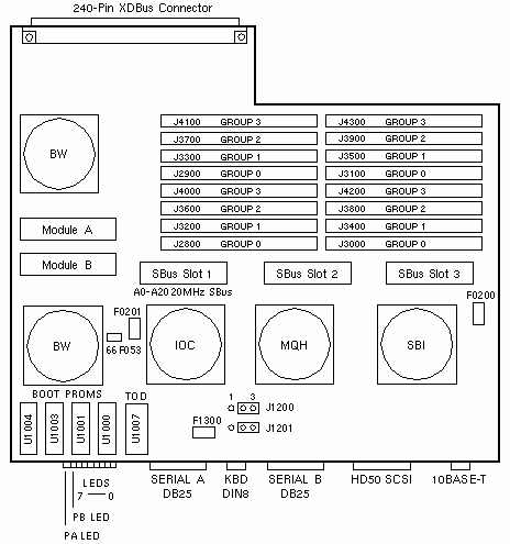
Jumper Settings
| JUMPER |
PINS |
SETTING |
DESCRIPTION |
J1200
J1201
J1200
J1201 |
1-2
1-2
2-3
2-3 |
Out
Out
In
In |
RS-423
RS-423
RS-232 (+12V) (default)
RS-232 (-12V) (default) |
Configured System Boards
PART
NUMBER |
MAIN
MEMORY |
SIMM
SIZE |
SPARC
MODULE |
| 501-2245-03 |
32MB |
8MB |
1 SM41 |
| 501-2247-03 |
64MB |
8MB |
2 SM41 |
| 501-2248-03 |
128MB |
32MB |
2 SM41 |
| 501-2429-xx |
64MB |
8MB |
2 SM41 |
| 501-2430-xx |
512MB |
32MB |
2 SM41 |
| 501-2245-04 |
32MB |
8MB |
1 SM51 |
| 501-2247-04 |
64MB |
8MB |
2 SM51 |
| 501-2248-04 |
128MB |
32MB |
2 SM51 |
| 501-2736-xx |
64MB |
8MB |
2 SM61 |
| 501-2737-xx |
128MB |
32MB |
2 SM61 |
Notes
- The minimum operating system is Solaris 2.2 (SunOS 5.2).
- Install the highest level Boot PROM set in System Board 0.
- Use SPARC module and SBus board Standoff 330-1664-01.
- A root partition >2GB is not supported by Sun-4c, 4m, or 4d systems.
Memory Configuration Notes
- The minimum memory configuration is 4 SIMMs in Group 0.
- Use 8MB SIMM 501-1817 and 32MB SIMM 501-2196.
- Install all Group 0 SIMMs on all system boards from the lowest board slot
number to the highest. Then install SIMMs in Group 1 on all system boards,
followed by Group 2 and Group 3. Refer to the Memory Module Installation
Guide for installation performance guidelines.
References
 SPARCserver 1000 Installation Manual, 801-2893.
-
SPARCserver 1000 System Board Manual, 801-2900.
-
Memory Module (SIMM) Product Note, 801-5345.
-
Memory Module Installation Guide, 801-2030.
- BugID 4035259 filed against root partition >2GB.
40MHz Control Board
SPARCserver 1000
| 501-1979 |
501-2412 |
| Programmed |
Unprogrammed |
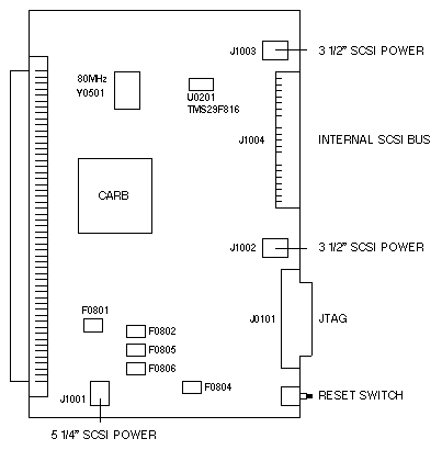
Notes
- The 40MHz Control Board is not compatible with the SS1000E System Board.
- The HOSTID and Ethernet Address are programmed into a 2KB x 8-bit Flash
EEPROM in the TMS29F816 at U0201. The TMS29F816 is not field replaceable.
- The HOSTID and Ethernet Address are downloaded from the control board to
the NVRAM on all system boards during POST.
- If the control board EEPROM content is invalid, the values stored in the
NVRAM on System Board 0 are used.
- The Yellow LED on the keyswitch interface board is ON if the control board
EEPROM content is invalid.
- Use the update-system-idprom OBP command to download the contents
of the NVRAM on System Board 0 to a control board with an invalid EEPROM. OBP
2.11 is required.
- Use the following command sequence to invalidate the control board EEPROM:
- ok patch noop call update-system-idprom
- ok patch noop call update-system-idprom
- ok patch call noop update-system-idprom
Power the system off and remove the Control Board.
- Use the following commands to change the NVRAM parameter that defines the
location of the master system board:
- ok clear-master-nvram
- ok reset
|