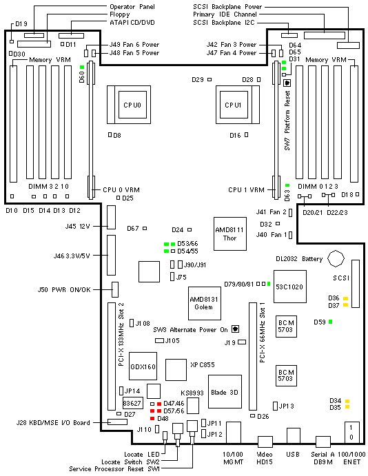
Sun Fire V20z
| 501-6840 |
Newisys S01357 / S00401 / S00189 / S00190
370-6730 w/o BIOS
A55A-AA Chassis FRU 380-0979
A55B-AA Chassis FRU 380-0979
MAC Address 00093dxxxxxx |

Jumpers
| LOCATION |
PINS |
SETTING |
DESCRIPTION |
| J19 |
1-2
1-2 |
Out
In |
Port A is Port A (default)
Port A is Service Processor Console |
| J108 |
2-3
2-3 |
In
Out |
Net Power Usage Indicator enabled (default)
Net Power Usage Indicator disabled |
| J110 |
1-2
2-3 |
In
In |
Clear CMOS on next boot
Normal CMOS Operation (default) |
| JP11 * |
1-2
1-2 |
In
Out |
BIOS Main Body Write Enabled (default)
BIOS Main Body Write controlled by BIOS or SP |
| JP12 * |
1-2
1-2 |
In
Out |
BIOS Boot Block Write Enabled (default)
BIOS Boot Block Write controlled by SP |
* Leave JP11 and JP12 in the default position.
HyperTransport/PCI Interrupt Map
| HT/PCI BRIDGE |
DEVICE |
IRQ A |
IRQ B |
IRQ C |
IRQ D |
| AMD-8131 Golem 0-B |
PCI Slot 2 |
x |
x |
x |
x |
| AMD-8131 Golem 0-A |
BCM5703 Ethernet 0 |
|
x |
|
|
| AMD-8131 Golem 0-A |
BCM5703 Ethernet 1 |
|
|
x |
|
| AMD-8131 Golem 0-A |
53C1020 SCSI |
|
|
|
x |
| AMD-8131 Golem 0-A |
PCI Slot 1 |
x |
x |
x |
x |
Installing a 33MHz card in Slot 1 forces Bus A to operate at 33MHz and
affects performance of the BCM5703 Ethernet controllers.
LEDs
| LOCATION |
COLOR |
STATE |
DESCRIPTION |
| D8 |
Amber |
Fault |
CPU0 Status |
| D10 |
Amber |
Fault |
CPU0 Memory VRM Status |
| D11 |
Amber |
Fault |
DVD Status |
| D12-15 |
Amber |
Fault |
CPU0 DIMM 0-3 Status |
| D16 |
Amber |
Fault |
CPU1 Status |
| D18 |
Amber |
Fault |
CPU1 Memory VRM Status |
| D19 |
Amber |
Fault |
Floppy Status |
| D20-23 |
Amber |
Fault |
CPU1 DIMM 0-3 Status |
| D26 |
Amber |
Fault |
PCI Slot 1 Status |
| D27 |
Amber |
Fault |
PCI Slot 2 Status |
| D32 |
Red |
Error |
Fan at full speed |
| D34 |
Yellow |
Normal |
Gigabit Ethernet 0 Mode |
| D35 |
Yellow |
Normal |
Gigabit Ethernet 0 Link |
| D36 |
Yellow |
Normal |
Gigabit Ethernet 1 Mode |
| D37 |
Yellow |
Normal |
Gigabit Ethernet 1 Link |
| D46 |
Red |
Normal |
Service Processor Status |
| D47 |
Red |
Unknown |
Service Processor Status |
| D48 |
Red |
Normal |
Service Processor Status |
| D53 |
Green |
Normal |
Power Supply POWER OK |
| D54 |
Green |
Normal |
Power On Indicator |
| D55 |
Yellow |
Reset |
Reset Indicator |
| D56 |
Red |
Normal |
Ethernet Connected to Upper MGMT Port |
| D57 |
Red |
Normal |
Ethernet Connected to Lower MGMT Port |
| D59 |
Green |
Normal |
AMD-8111 RAM Power On |
| D60 |
Green |
Normal |
CPU0 VRM Power OK |
| D63 |
Green |
Normal |
CPU1 VRM Power OK |
| D66 |
Green |
Normal |
AMD-8111 Power OK |
| D67 |
Red
Red |
Error
Reset |
Power Reset Sequencer Internal Error
SW1 Service Processor Reset Pressed |
| D79 |
Green |
Normal |
53C1020 SCSI Channel A Indicator |
| D81 |
Green |
Normal |
53C1020 SCSI Controller Operational |
Notes:
The normal state of D46 and D48 is an illuminated Red LED.
The normal state of D56 is a illuminated Red LED when a cable is connected.
The normal state of D57 is a illuminated Red LED when a cable is connected.
|
|
Sun Fire V20z Codename: Stinger2P |
Notes
- The Sun Fire V20z System Board is not a Field Replaceable Unit.
- Press F2 during bootup to enter the BIOS menu.
- BIOS updates are available at
 V20z SW 2.8.2 - Bundles. V20z SW 2.8.2 - Bundles.
- Due to AMD-8131 Errata 56, four-function PCI-X option cards are not
supported on the Sun Fire V20z.
See  Release Notes
for details about Errata 56. Release Notes
for details about Errata 56.
PCI Slot Notes
- The Slot 1 PCI Card Guide is installed on System Board 501-6840
near D36 and D37.
- The Slot 1 PCI Card Guide is not installed on System Board 501-7039.
- The Slot 1 PCI Card Guide limits the card length to approximately 172 mm.
- The Dual SCSI/Dual FastEthernet Option 2222 length is approximately 178 mm.
References
 Sun Fire V20z and V40z Servers Release Notes, 819-1771.
 Sun Fire V20z Server Installation Guide, 817-5246.
 Sun Fire V20z Server User Guide, 817-5248.
 Sun Fire V20z Server Management Guide, 817-5249.
 Sun Fire V20z and V40z Servers Troubleshooting Techniques and Diagnostics Guide, 817-7184.
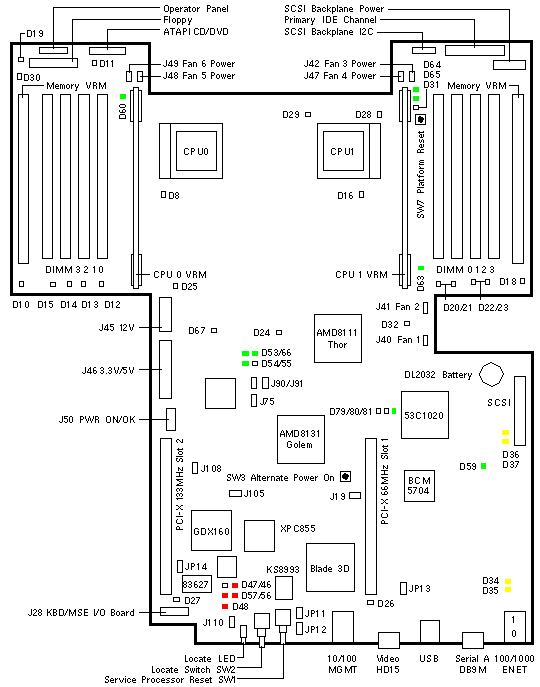
Sun Fire V20z
| 501-7039 |
Newisys S02398 / S02035 / S02009
370-7691 w/o BIOS
A55D-AA Chassis FRU 380-1168
MAC Address 00093dxxxxxx |

Jumpers
| LOCATION |
PINS |
SETTING |
DESCRIPTION |
| J19 |
1-2
1-2 |
Out
In |
Port A is Port A (default)
Port A is Service Processor Console |
| J108 |
2-3
2-3 |
In
Out |
Net Power Usage Indicator enabled (default)
Net Power Usage Indicator disabled |
| J110 |
1-2
2-3 |
In
In |
Clear CMOS on next boot
Normal CMOS Operation (default) |
| JP11 * |
1-2
1-2 |
In
Out |
BIOS Main Body Write Enabled (default)
BIOS Main Body Write controlled by BIOS or SP |
| JP12 * |
1-2
1-2 |
In
Out |
BIOS Boot Block Write Enabled (default)
BIOS Boot Block Write controlled by SP |
* Leave JP11 and JP12 in the default position.
HyperTransport/PCI Interrupt Map
| HT/PCI BRIDGE |
DEVICE |
IRQ A |
IRQ B |
IRQ C |
IRQ D |
| AMD-8131 Golem 0-B |
PCI Slot 2 |
x |
x |
x |
x |
| AMD-8131 Golem 0-A |
BCM5704 Ethernet 0 |
|
x |
|
|
| AMD-8131 Golem 0-A |
BCM5704 Ethernet 1 |
|
|
x |
|
| AMD-8131 Golem 0-A |
53C1020 SCSI |
|
|
|
x |
| AMD-8131 Golem 0-A |
PCI Slot 1 |
x |
x |
x |
x |
Installing a 33MHz card in Slot 1 forces Bus A to operate at 33MHz and
affects performance of the BCM5703 Ethernet controllers.
LEDs
| LOCATION |
COLOR |
STATE |
DESCRIPTION |
| D8 |
Amber |
Fault |
CPU0 Status |
| D10 |
Amber |
Fault |
CPU0 Memory VRM Status |
| D11 |
Amber |
Fault |
DVD Status |
| D12-15 |
Amber |
Fault |
CPU0 DIMM 0-3 Status |
| D16 |
Amber |
Fault |
CPU1 Status |
| D18 |
Amber |
Fault |
CPU1 Memory VRM Status |
| D19 |
Amber |
Fault |
Floppy Status |
| D20-23 |
Amber |
Fault |
CPU1 DIMM 0-3 Status |
| D26 |
Amber |
Fault |
PCI Slot 1 Status |
| D27 |
Amber |
Fault |
PCI Slot 2 Status |
| D32 |
Red |
Error |
Fan at full speed |
| D34 |
Yellow |
Normal |
Gigabit Ethernet 0 Mode |
| D35 |
Yellow |
Normal |
Gigabit Ethernet 0 Link |
| D36 |
Yellow |
Normal |
Gigabit Ethernet 1 Mode |
| D37 |
Yellow |
Normal |
Gigabit Ethernet 1 Link |
| D46 |
Red |
Normal |
Service Processor Status |
| D47 |
Red |
Unknown |
Service Processor Status |
| D48 |
Red |
Normal |
Service Processor Status |
| D53 |
Green |
Normal |
Power Supply POWER OK |
| D54 |
Green |
Normal |
Power On Indicator |
| D55 |
Yellow |
Reset |
Reset Indicator |
| D56 |
Red |
Normal |
Ethernet Connected to Upper MGMT Port |
| D57 |
Red |
Normal |
Ethernet Connected to Lower MGMT Port |
| D59 |
Green |
Normal |
AMD-8111 RAM Power On |
| D60 |
Green |
Normal |
CPU0 VRM Power OK |
| D63 |
Green |
Normal |
CPU1 VRM Power OK |
| D66 |
Green |
Normal |
AMD-8111 Power OK |
| D67 |
Red
Red |
Error
Reset |
Power Reset Sequencer Internal Error
SW1 Service Processor Reset Pressed |
| D79 |
Green |
Normal |
53C1020 SCSI Channel A Indicator |
| D81 |
Green |
Normal |
53C1020 SCSI Controller Operational |
Notes:
The normal state of D46 and D48 is an illuminated Red LED.
The normal state of D56 is a illuminated Red LED when a cable is connected.
The normal state of D57 is a illuminated Red LED when a cable is connected.
|
|
Sun Fire V20z Codename: Stinger2P |
Notes
- The Sun Fire V20z System Board is not a Field Replaceable Unit.
- Press F2 during bootup to enter the BIOS menu.
- BIOS updates are available at
 V20z SW 2.8.2 - Bundles. V20z SW 2.8.2 - Bundles.
- Due to AMD-8131 Errata 56, four-function PCI-X option cards are not
supported on the Sun Fire V20z.
See  Release Notes
for details about Errata 56. Release Notes
for details about Errata 56.
- The BCM5704 Ethernet Controller on System Board 501-7039 requires an
Install-Time Update (ITU) to install Solaris 9 4/04 x86 or
Solaris 9 9/04 x86.
Refer to FIN I1154.
- System Board 501-7039 is installed in Chassis FRU 380-1168.
PCI Slot Notes
- The Slot 1 PCI Card Guide is installed on System Board 501-6840
near D36 and D37.
- The Slot 1 PCI Card Guide is not installed on System Board 501-7039 or
501-7125.
- The Slot 1 PCI Card Guide limits the card length to approximately 172 mm.
- The Dual SCSI/Dual FastEthernet Option 2222 length is approximately 178 mm.
References
 Sun Fire V20z and V40z Servers Release Notes, 819-1771.
 Sun Fire V20z Server Installation Guide, 817-5246.
 Sun Fire V20z Server User Guide, 817-5248.
 Sun Fire V20z Server Management Guide, 817-5249.
 Sun Fire V20z and V40z Servers Troubleshooting Techniques and Diagnostics Guide, 817-7184.
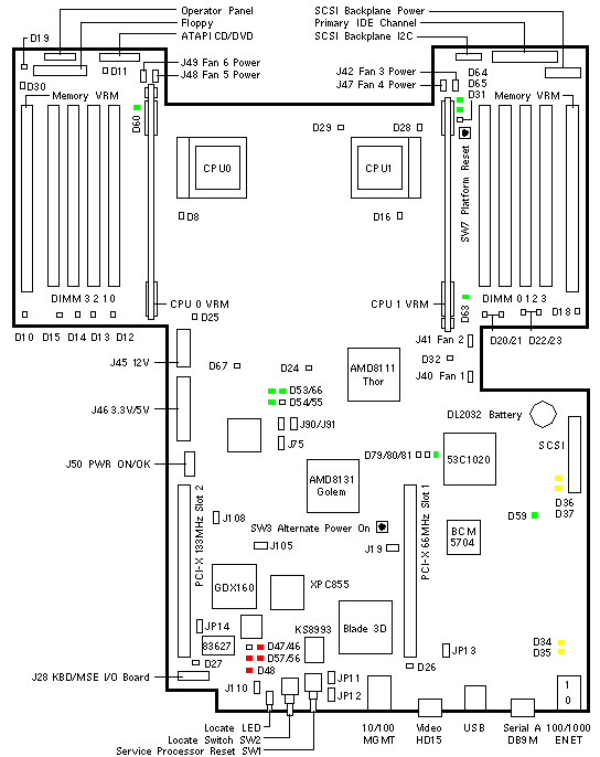
Sun Fire V20z
| 501-7125 |
Newisys S02595 / S02615
370-7788 w/o BIOS
A55E-AA Chassis FRU 380-1194
MAC Address 00093dxxxxxx |

Jumpers
| LOCATION |
PINS |
SETTING |
DESCRIPTION |
| J19 |
1-2
1-2 |
Out
In |
Port A is Port A (default)
Port A is Service Processor Console |
| J108 |
2-3
2-3 |
In
Out |
Net Power Usage Indicator enabled (default)
Net Power Usage Indicator disabled |
| J110 |
1-2
2-3 |
In
In |
Clear CMOS on next boot
Normal CMOS Operation (default) |
| JP11 * |
1-2
1-2 |
In
Out |
BIOS Main Body Write Enabled (default)
BIOS Main Body Write controlled by BIOS or SP |
| JP12 * |
1-2
1-2 |
In
Out |
BIOS Boot Block Write Enabled (default)
BIOS Boot Block Write controlled by SP |
* Leave JP11 and JP12 in the default position.
HyperTransport/PCI Interrupt Map
| HT/PCI BRIDGE |
DEVICE |
IRQ A |
IRQ B |
IRQ C |
IRQ D |
| AMD-8131 Golem 0-B |
PCI Slot 2 |
x |
x |
x |
x |
| AMD-8131 Golem 0-A |
BCM5704 Ethernet 0 |
|
x |
|
|
| AMD-8131 Golem 0-A |
BCM5704 Ethernet 1 |
|
|
x |
|
| AMD-8131 Golem 0-A |
53C1020 SCSI |
|
|
|
x |
| AMD-8131 Golem 0-A |
PCI Slot 1 |
x |
x |
x |
x |
Installing a 33MHz card in Slot 1 forces Bus A to operate at 33MHz and
affects performance of the BCM5703 Ethernet controllers.
LEDs
| LOCATION |
COLOR |
STATE |
DESCRIPTION |
| D8 |
Amber |
Fault |
CPU0 Status |
| D10 |
Amber |
Fault |
CPU0 Memory VRM Status |
| D11 |
Amber |
Fault |
DVD Status |
| D12-15 |
Amber |
Fault |
CPU0 DIMM 0-3 Status |
| D16 |
Amber |
Fault |
CPU1 Status |
| D18 |
Amber |
Fault |
CPU1 Memory VRM Status |
| D19 |
Amber |
Fault |
Floppy Status |
| D20-23 |
Amber |
Fault |
CPU1 DIMM 0-3 Status |
| D26 |
Amber |
Fault |
PCI Slot 1 Status |
| D27 |
Amber |
Fault |
PCI Slot 2 Status |
| D32 |
Red |
Error |
Fan at full speed |
| D34 |
Yellow |
Normal |
Gigabit Ethernet 0 Mode |
| D35 |
Yellow |
Normal |
Gigabit Ethernet 0 Link |
| D36 |
Yellow |
Normal |
Gigabit Ethernet 1 Mode |
| D37 |
Yellow |
Normal |
Gigabit Ethernet 1 Link |
| D46 |
Red |
Normal |
Service Processor Status |
| D47 |
Red |
Unknown |
Service Processor Status |
| D48 |
Red |
Normal |
Service Processor Status |
| D53 |
Green |
Normal |
Power Supply POWER OK |
| D54 |
Green |
Normal |
Power On Indicator |
| D55 |
Yellow |
Reset |
Reset Indicator |
| D56 |
Red |
Normal |
Ethernet Connected to Upper MGMT Port |
| D57 |
Red |
Normal |
Ethernet Connected to Lower MGMT Port |
| D59 |
Green |
Normal |
AMD-8111 RAM Power On |
| D60 |
Green |
Normal |
CPU0 VRM Power OK |
| D63 |
Green |
Normal |
CPU1 VRM Power OK |
| D66 |
Green |
Normal |
AMD-8111 Power OK |
| D67 |
Red
Red |
Error
Reset |
Power Reset Sequencer Internal Error
SW1 Service Processor Reset Pressed |
| D79 |
Green |
Normal |
53C1020 SCSI Channel A Indicator |
| D81 |
Green |
Normal |
53C1020 SCSI Controller Operational |
Notes:
The normal state of D46 and D48 is an illuminated Red LED.
The normal state of D56 is a illuminated Red LED when a cable is connected.
The normal state of D57 is a illuminated Red LED when a cable is connected.
|
|
Sun Fire V20z Codename: Stinger2P |
Notes
- The Sun Fire V20z System Board is not a Field Replaceable Unit.
- Press F2 during bootup to enter the BIOS menu.
- BIOS updates are available at
 V20z SW 2.8.2 - Bundles. V20z SW 2.8.2 - Bundles.
- Due to AMD-8131 Errata 56, four-function PCI-X option cards are not
supported on the Sun Fire V20z.
See  Release Notes
for details about Errata 56. Release Notes
for details about Errata 56.
- The BCM5704 Ethernet Controller on System Board 501-7125 requires an
Install-Time Update (ITU) to install Solaris 9 4/04 x86 or
Solaris 9 9/04 x86.
Refer to FIN I1154.
- System Board 501-7125 is installed in Chassis FRU 380-1194.
PCI Slot Notes
- The Slot 1 PCI Card Guide is installed on System Board 501-6840
near D36 and D37.
- The Slot 1 PCI Card Guide is not installed on System Board 501-7039 or
501-7125.
- The Slot 1 PCI Card Guide limits the card length to approximately 172 mm.
- The Dual SCSI/Dual FastEthernet Option 2222 length is approximately 178 mm.
References
 Sun Fire V20z and V40z Servers Release Notes, 819-1771.
 Sun Fire V20z Server Installation Guide, 817-5246.
 Sun Fire V20z Server User Guide, 817-5248.
 Sun Fire V20z Server Management Guide, 817-5249.
 Sun Fire V20z and V40z Servers Troubleshooting Techniques and Diagnostics Guide, 817-7184.
|

