Ultra 20 (A63)
| 375-3306 |
375-3419 |
|
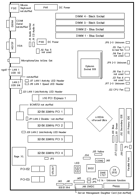
Tyan Tomcat K8E S2865 |
Tyan Tomcat K8E S2865 |

Connectors
| LOCATION |
DESCRIPTION |
| J8 |
Front Panel Audio |
| J9 |
Audio In from CD/DVD |
| J13 |
Front Fan 1 |
| J22 |
CPU Fan |
| J17/J28 |
Front Panel LAN1/LAN2 Link and Activity LED |
| J19/J23 |
Front Panel LAN1/LAN2 Speed LED |
| J30/J31 |
SATA1 / SATA2 |
| J34/J35 |
USB3 not installed / Yellow USB4 to Front Panel USB |
| J37/J38 |
SATA3 / SATA4 not used |
| J40 |
COM2 Serial Port |
| J41/J43 |
IEEE 1394-2 and IEEE 1394-1 |
| J45 |
Front Panel Header |
Jumper Settings
| JUMPER |
PINS |
SETTING |
DESCRIPTION |
| JP2 |
1-2
2-3 |
In
In |
Normal CMOS (default)
Clear CMOS (temporary setting only) |
| JP3 |
1-2
2-3 |
In
In |
Select 3.3V PCI Slot (default)
Select 5.0V PCI Slot |
|
Ultra 20 Codename: Marrakesh |
Notes
- The minimum Solaris operating system is Solaris 10 3/05 x64.
- Install a single DIMM in any slot.
- A three DIMM memory configuration is not supported.
- Install the first DIMM pair in slots DIMM 1 and DIMM 2.
- Install the second DIMM pair in slots DIMM 3 and DIMM 4.
- Mouse 370-3632 is not qualified for use on the Ultra 20.
Use Mouse 371-0754.
- The LAN2 function on the USB3/USB4 connector is not installed.
Clearing CMOS Notes
- Power off the system and disconnect the AC power cord.
- Move the jumper at JP2 to Pin 2 and Pin 3 for several seconds.
- Move the jumper at JP2 back to Pin 1 and Pin 2.
- Reconnect the AC power cord.
References
 Ultra 20 User Guide, 819-2146.
 Ultra 20 Release Notes, 819-2147.
 Ultra 20 Getting Started Guide, 819-2148.
|

